About
Toy3D is a simple 3D engine built using Swift, Metal and MetalKit. Toy3D is not intended to be a high performance 3D engine or even used in any real application, it doesn’t have any fancy optimizations or a large feature set.
Its purpose is to allow someone to work through the basics of creating a simple 3D engine and learn about the core concepts of Metal and hopefully the code is simple enough that you can open the source and easily follow along.
The reason why creating a simple 3D engine is a great learning experience is because most tutorials will show you the basics and get a triangle or cube rendering on the screen, which is great, but then actually trying to use that information to render >1 objects is another leap. How do you organize your code to handle encoding more than one model, what are the lifetime of different objects, how can you efficiently send multiple draw calls to the GPU etc.
It is assumed that you have a basic understanding of 3D math concepts such as Vectors and Matrices. If not then I would recommend this book Essential Math for Games Programmers. It’s a really great resource for all of the core math concepts you will use in a 3D engine.
Source
You can find all of the source code for the engine https://github.com/markdaws/Toy3D. It is setup as a Swift package so you can easily include it in your own code.
There is an example project that uses the library and creates some simple 3D scenes here: https://github.com/markdaws/metal-example
If you find any issues or have any questions feel free to create some issues in the repository.
Software Versions
The following software versions were used at the time of writing:
-
Xcode 11
-
Swift 5.1
-
iOS 12
Resources
Here are a list of resources for Swift + Metal
3D Fundamentals
Before we talk about Metal or the implementation of our 3D engine we need to understand a few core concepts around 3D graphics, along with the basics of how you take points in a 3D space and convert them to pixels on a 2D screen.
If you are already familiar with how 3D graphics work at a high level, then feel free to skip this whole section.
Defining a 3D Model
The first thing we need to do in order to render a 3D model to the screen is define what data we need and how to organize that data. Let’s look at a 3D model and see how it works. A great source of online 3D models is Sketchfab, we will use this model of a house as an example.
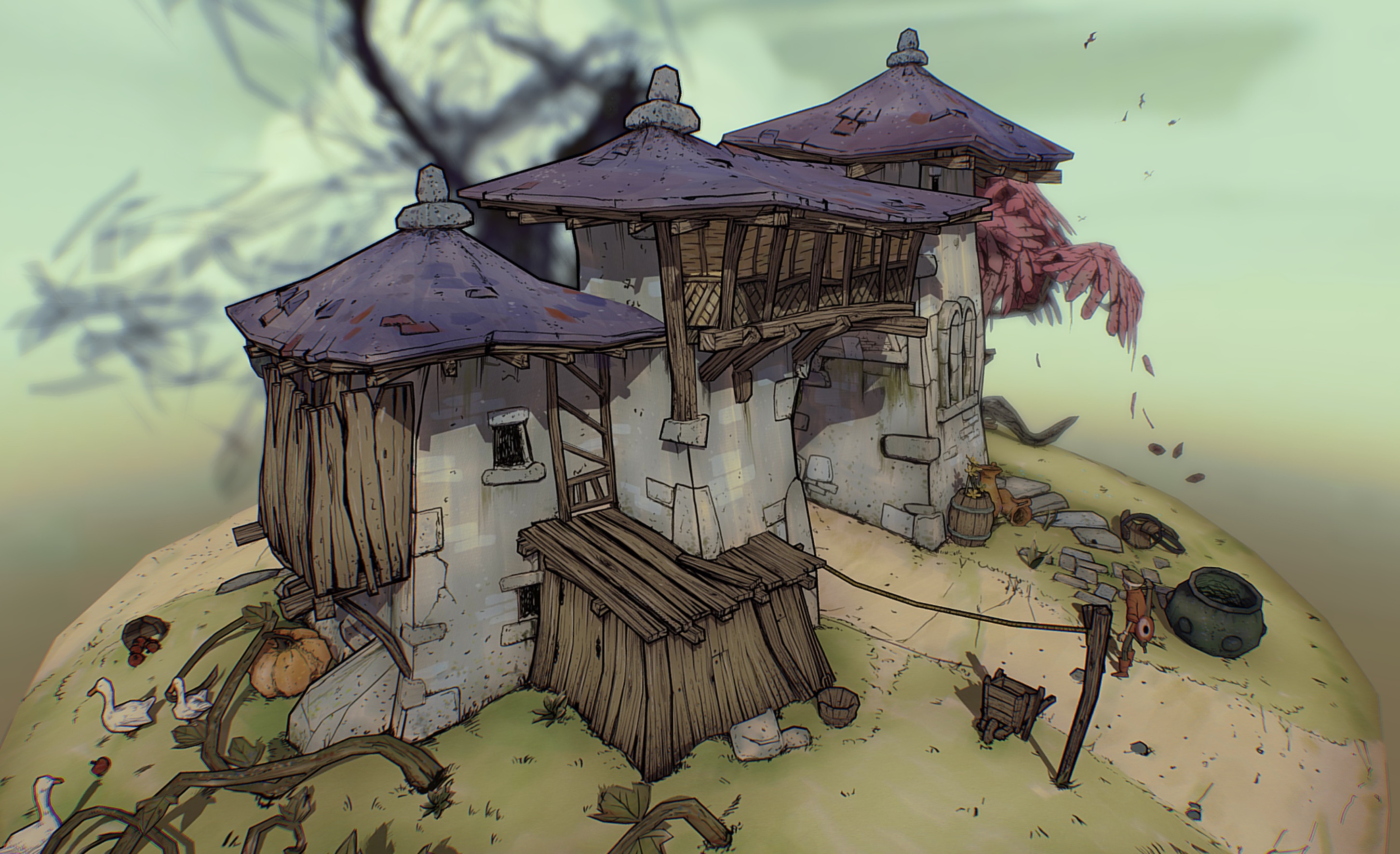
| If you visit the model on Sketchfab, their viewer has a model inspector option in the bottom right that exposes all the underlying model information, it is really fun to play around with. |
The first thing we need to define are the individual 3D x,y,z values that make up the model, the vertices. When creating your 3D model in some modelling tool (or by hand!) we draw the content and end up with a long list of 3D points. Along with the 3D points you also have to specify how these points are connected together to actually draw something more than just points (you would end up with a point cloud if you did that). Typically GPUs like to process data in terms of triangles, they are a simple mathematical concept that have several simple properties that make them very fast to convert from 3D to points on a 2D screen.
So given a list of 3D points we also specify how those points connect, we specify the primitive, like a triangle and then let the GPU know which points correspond to which triangle. This can be done by the implicit order of the 3D points in your vertex buffer e.g. p0, p1, p2 is triangle0, p3, p4, p5 is triangle1 and so on, or you can define an index buffer, which uses the index into the vertex buffer to define the triangles. This has the advantage that you can use the same 3D point in more than one triangle, whereas with the previous method you would have to duplicate points.
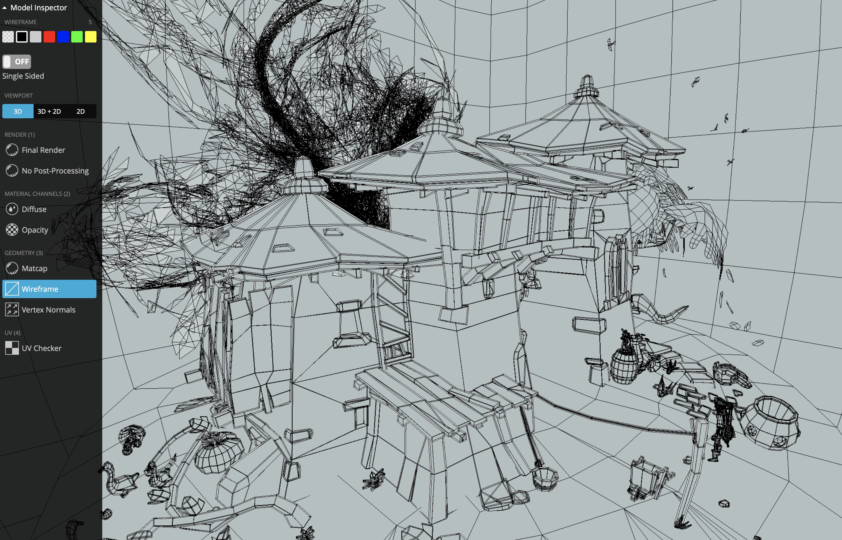
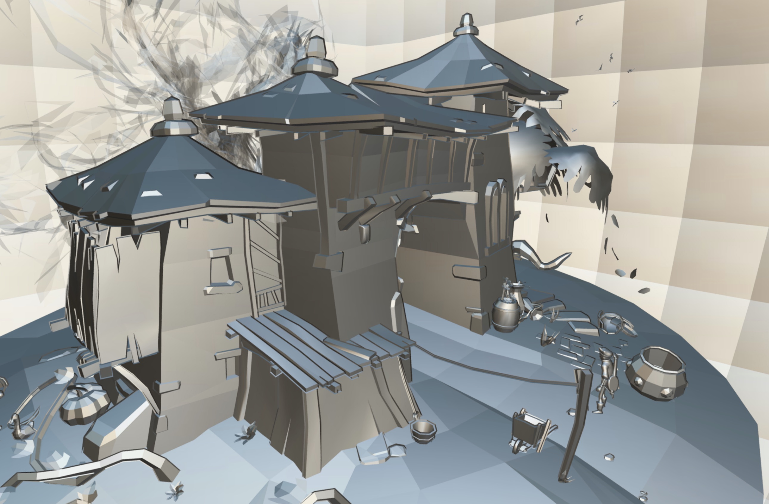
Below is an example of taking the 3D points and defining how they are connected and rendering a plain model.
Now that we can draw the geometry of the model, we want to make it look a bit more interesting. This can be done by either just giving each point in a model a fixed color, or you can also specify that the 3D point should map to a 2D position in a texture, then use the texture to paint on to the model.
In the example below you can see the red dot on the left in the 3D model and on the right how the red dot is actually mapped to a 2D coordinate in the texture.
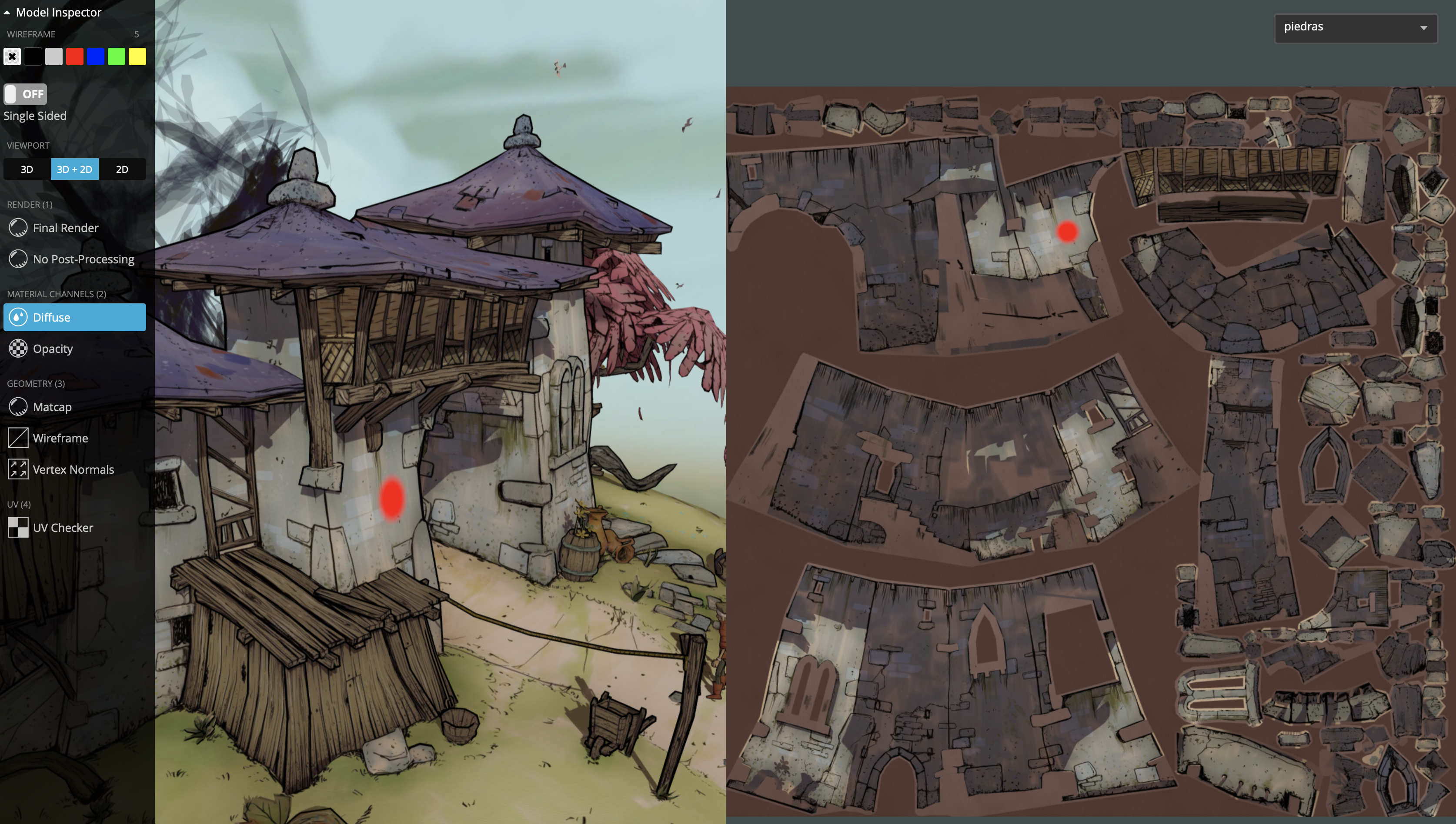
You can see how the 2D texture is filled with pieces of the 3D model surface. Typically 3D modelling tools will generate these for you.
Given this information we can see that our vertices are not only 3D positions but also other information. If we generate a number of vertices for our model it might look something like position:uv:normal
[x0,y0,z0,u0,v0,nx0,ny0,nz0,x1,y1,z1,u1,v1,nx1,ny1,nz1, … ]
| Texture coordinates are usually called u and v, with u being a horizontal offset into the texture and v being a vertical offset. NOTE: We haven’t discussed normals yet, but (nx0, nxy0, nz0) is a vector that you can define for each vertex that defines how light behaves with the model. |
With this information in mind you can see that a 3D API like Metal is concerned with efficiently taking all of the vertex information and associated content such as textures and trying to convert those into 2D images as fast as possible.
Local vs. World Space
When 3D objects are created in a modelling tool, the points in the object are all relative to a "local" origin. This is commonly referred to as local / object / model space. The model is generally created so that the origin and axis make manipulating the object easier.
The local origin is normally either placed in the center of the object, if it’s something you want to rotate around the center e.g. a ball, or at the bottom of the object, for example if you modelled a vase having the origin at the bottom easily lets you place the object on another surface like a table without any extra manipulation.
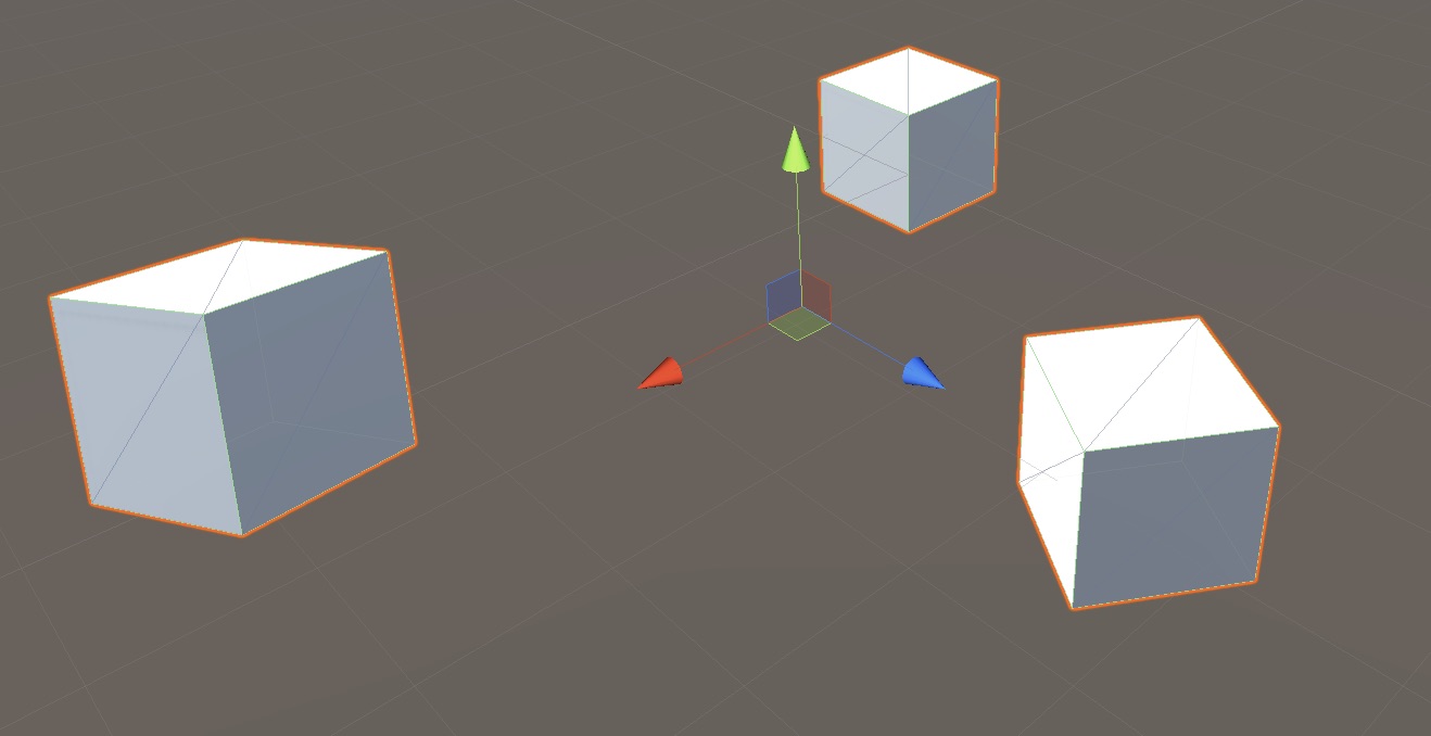
When constructing our global 3D world with many individual objects in it, we have one world origin and set of axis x,y and z that are used by all objects. This axis and origin act as a common reference amongst all objects in the world.
As models are placed in the world we transform their local points to world points using rotation, scaling and translation. This is known as their model transform. For example, if we modelled a 3D ball, the local origin of [0,0,0] might be in the center of the ball when we define all the 3D points in the ball, but when it’s placed in the world its origin might now be at [10,5,3].
One way to think of this would be if you were modelling a scene with multiple chairs, you would first create a single chair model, probably with the origin at the bottom of the legs to make it easy to put the chairs on the floor plane. If we just insert multiple chairs in the world without any additional transforms, they would all overlap at the world origin since their 3D points would all be the same, we would only see one chair. One way to work around this would be to actually define all of the points in the model in world space when you create it, but that would mean you would have to make N individual chair models, you couldn’t reuse just one instance of the model.
Instead we insert multiple instances of the same chair model, but on each chair we would set a different translation, scaling and rotation to transform each local chair to a final position in the world. Their "local" 3D points are still all the same, but their final world 3D points now differ.
Object Hierarchies
We have talked about how an object is initially defined in local space, then we applied a set of transforms to define its appearance in world space. However, it’s possible to apply more than one level of transforms to an object to affect its final appearance in world space. We can specify an objects transform as being relative to a parent or ancestor objects.
For example, if we were making a static model of a subset of the solar system, you could draw the sun, earth and moon and place them in a scene with the following hierarchy:
Solar System
 -> Sun
 -> Earth
 -> Moon
Each item would then have a single transform applied to it to move it to a final world position.
However if you now wanted to animate the scene so that the sun rotates in place, the earth rotates around the sun and the moon around the earth, you would have to manually calculate the transforms each frame, taking in to account how the entity should move relative to the other entities. This is a lot of duplicated calculation and makes the code more complicated.
A simpler way to model the scene would be instead with the following hierarchy:
Solar System
 -> Sun
  -> Earth
    -> Moon
Now to calculate the final world position of an entity, you start at the bottom and traverse up the hierarchy applying the transform at each level until you end up with one overall transform.
For example, if you wanted to calculate the overall world transform of the moon, you would do the following (transforms are applied from right to left):
World Transform = Tsun * Tearth * Tmoon
| T represents a transform, some combination of scaling, rotation and translation. Transforms are applied right to left in this case. |
This makes everything very simple, as we rotate the sun, the earth and moon automatically get their final world transform updated without us having to explicitly set a new transform on them.
We will use this concept in our 3D engine to create a simple scene graph.
Eye / Camera Space
Now that we have all of the 3D points of our models in a single unified world space, we need to move on to the next step in our journey of figuring out how to get those 3D points on a 2D screen.
Just as we see the real world through the viewpoint of our location in the world and the position and orientation of our eyes we need to define where our 3D scene will be viewed from. This is done by defining a camera object.
To define the camera we need a few basic properties:
- Origin
-
The location of the camera in 3D space (x, y, z).
- Look Direction
-
A 3D vector specifying in which direction the camera is looking.
- Up Vector
-
Given a look direction we also need some way to specify the rotation of the camera. If you imagine a look vector shooting out of your eyes, the look vector doesn’t change even as you tilt your head left or right. The up vector helps clarify the camera rotation, normally this can just be set to (0,1,0).
In our engine we are going to use a right hand coordinate system, this is where +x points to the right, +y is up and +z points towards the camera. We could use a left handed coordinate system, it doesn’t really matter since at the end of the day we have to transform the points to the same representation the GPU expects, it would just change some of the matrices below.
To convert a point from world space to eye space we can use the following matrix transformation:
static func makeLook(
  eye: Vec3,
  look: Vec3,
  up: Vec3
) -> Mat4 {

  let vLook = normalize(look)
  let vSide = cross(vLook, normalize(up))
  let vUp = cross(vSide, vLook)

  var m = Mat4([
    Vec4(vSide, 0),
    Vec4(vUp, 0),
    Vec4(-vLook, 0),
    Vec4(0, 0, 0, 1)
  ])
  m = m.transpose

  let eyeInv = -(m * Vec4(eye, 0))
  m[3][0] = eyeInv.x
  m[3][1] = eyeInv.y
  m[3][2] = eyeInv.z
  return m
}
I’m not going to go over the math to create this transform, but there are a vast number of resources on line if you want to find out more.
Needless to say, it is basically just subtracting the position of the camera from each point, to make the points relative the origin of the camera instead of the world origin, then rotating each point so that the camera up vector is considered up instead of the world up e.g. [0, 1, 0].
Projection (3D → 2D)
Now we have taken the points in 3D world space and converted them in to values relative to a cameras view point, we need to now take a point in 3D and convert it in to a representation on a 2D plane so that it can be rendered on a screen. The process of transforming 3D points to 2D space is called projection.
We will project points as we see them in the real world using Perspective Projection. This is where parallel lines seem to converge to a point as they move further away from the viewing position.

In order to calculate our 3D → 2D transform we can think of the problem as taking the camera and having a flat plane on which all of the 3D points will be projected. We will want this plane to have the same aspect ratio (width/height) as the screen we are rendering to so that they match. We will also want to define some other planes, a far plane which specifies that any object further than this plane we don’t want to render. Theoretically we don’t need this, we could render everything but in graphics we generally want to limit the number of object we render for performance purposes. We also need a near plane, this stops objects too close to the camera being rendered which can cause weird issues with division by 0 etc. These two planes will be controlled by values zNear and zFar.
The last piece of information we need is a field of view. The field of view specifies how wide or narrow the camera can view. If you have a narrow field of view it is like zooming the camera in, making the field of view larger is like zooming out on the camera.
Given this we end up with something like below:
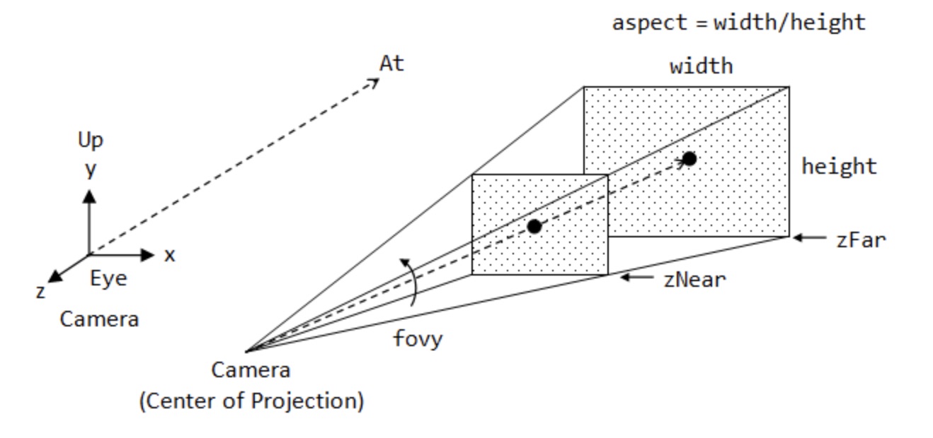
This defines a view frustum in the near, far, top, right, bottom and left planes. This view frustum can also be used by the GPU to clip any parts of the 3D scene that are not visible. If the points are outside of this view frustum then they can be ignored by the GPU.
To do this we want our projected points inside the view frustum to map to values defined by Metals clip space (as we will see later this is what we want to end up with and output from our Vertex Shader):
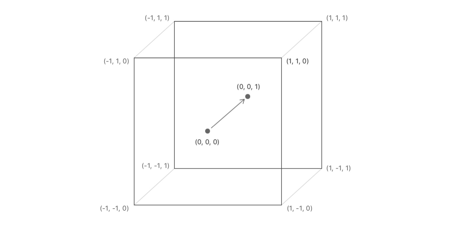
I’m not going to go in how to derive the math here, there are many resources online to look at, but for our purposes the math we will use looks like:
static func makePerspective(
  fovyDegrees fovy: Float,
  aspectRatio: Float,
  nearZ: Float,
  farZ: Float
) -> Mat4 {
  let ys = 1 / tanf(Math.toRadians(fovy) * 0.5)
  let xs = ys / aspectRatio
  let zs = farZ / (nearZ - farZ)
  return Mat4([
    Vec4(xs,  0, 0,   0),
    Vec4( 0, ys, 0,   0),
    Vec4( 0,  0, zs, -1),
    Vec4( 0,  0, zs * nearZ, 0)
  ])
}| As you can see this function is dependant on the aspect ratio of the screen, so if that changes we need to make sure that we update this calculation. |
Summary
In summary, to take a local point in 3D and end up with it transformed to values we can use to render to the screen we perform (from right to left):
LocalToClipSpace = Tprojection * Tview * Tmodel
I’ve skipped over a lot of the details here but I would recommend this book if you want to dive more into the math around this: Essential Math for Games Programmers.
Metal
What is Metal?
Metal is a low-level, low-overhead hardware-accelerated 3D graphic and compute shader application programming interface (API) developed by Apple Inc., and which debuted in iOS 8. Metal combines functions similar to OpenGL and OpenCL under one API.
Source: Wikipedia
You use the Metal API in your macOS, iOS or tvOS apps via Swift or Objective-C. The API lets you interact and send commands to the GPU. Along with the API you also need to write some Metal Shaders, this is done in the Metal Shader Language.
Apple’s aim with Metal was to replace OpenGL with a single API they owned and could control the roadmap for, that also allowed them to remove a lot of the overhead that comes with a cross platform framework with a long legacy.
Whether you want or need to use Metal depends on your use case. Obviously if you are looking for a cross platform framework that could be used eventually on something like Android, Metal is not the way to go. However if you are Apple focussed or building a graphical abstraction where Metal might be one of the compile targets Metal will help you get the absolute highest performance for your graphical application.
As well as Metal, Apple also has SceneKit another 3D graphics framework you can use to create content in your 3D app. This might be a good choice and it is now built on top of Metal, but being another level of abstraction above Metal you may come across limitations in the framework that hinder you or the apps performance. Building on the absolute lowest level gives you the ultimate freedom, however I have found SceneKit to be a really intuitive and fun framework to use for simple 3D apps.
What is MetalKit?
MetalKit is a framework that provides some helper classes that simply some common Metal use cases.
It mainly provides an easy way to load textures, handle loading 3D models from Model I/O and provides a MTKView class that makes creating a view capable of rendering Metal content very easy.
Shaders
Metal is a low level framework, most of the magic actually comes from running your code not on the CPU but the GPU. Just like you can compile and run code on your CPU, you can write programs and compile and run them on the GPU instead, these are referred to as shaders.
A GPU is a highly specialized piece of hardware which is massively parallelized to process complex 3D scenes (you can also run non graphical workloads on the GPU via compute shaders but we are not going to cover that here).
There are two main types of shaders you will use to render 3D content, the vertex shader and the fragment shader. The job of the vertex shader is to take 3D points in local space for a model and transform them into clip space (as we talked about earlier). Once the GPU has the transformed points, it can take some extra information such as how the points are connected together to make triangles and determine which points on the screen should be drawn (rasterization).
Once we have individual pixels, we can call the Fragment shader that will then determine what is the final color of the pixel, usually based on some lighting and materials associated with the model and scene.
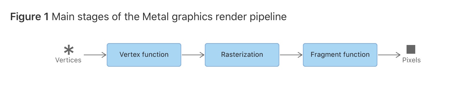
The main process here is to first create a buffer in code, basically a contiguous chunk of memory, fill that with 3D information e.g. [x0, y0, z0, x1, y1, z1, …] then send those values plus textures and other vertex attributes (color, normals) and the other matrices we looked at TModel, TView, TProjection to the GPU. Once on the GPU, each vertex information will be passed to the vertex function, it then applies the transforms ot the points and returns them to the GPU for rasterization. Finally the rasterized points end up passed in to the Fragment shader where we decide the final color for the pixel. This information is then written to a frame buffer and eventually rendered to the screen.
Metal shaders use the Metal Shader Language. MSL is based on C++14 with certain modifications and restrictions.
An example of a simple vertex and fragment shader that renders models with a solid color is shown below.
#include <metal_stdlib>
#include <simd/simd.h>

using namespace metal;

struct VertexIn { (1)
  float3 position [[attribute(0)]]; (2)
  float4 color [[attribute(1)]];
};

struct VertexOut { (3)
  float4 position [[position]]; (4)
  float4 color;
};

struct Uniforms { (5)
  float4x4 modelMatrix;
  float4x4 viewProjectionMatrix;
};

vertex VertexOut simple_vertex( (6)
  const VertexIn vIn [[ stage_in ]], (7)
  const device Uniforms& uniforms [[ buffer(0) ]] {  (8)

  VertexOut vOut;
  vOut.position = uniforms.viewProjectionMatrix * uniforms.modelMatrix * float4(vIn.position, 1.0); (9)
  vOut.color = vIn.color;
  return vOut;
}

fragment float4 simple_fragment(VertexOut fragIn [[stage_in]]) { (10)
  return fragIn.color; (11)
}Core Types
There are a number of core types you will interact with. They may initially look a bit verbose but they are actually pretty simple once you get the basic principles of Metal.
MTLDevice
A MTLDevice is a protocol that defines an abstraction around the GPU. It is used to create resources such as buffers to store 3D vertices, send drawing commands to the GPU, basically any interaction with the GPU is done through this interface.
This is the first object you will want to create and then keep a reference to it for the lifetime of your application. You can create multiple devices if you have multiple GPUs in your computer, but for most apps you will just have one main device.
Creating the device is very simple, call MTLCreateSystemDefaultDevice and verify that a device could be created:
guard let device = MTLCreateSystemDefaultDevice() else {
  print("Metal is not supported")
  return
}
MTLCommandQueue
In order to draw anything on the screen we have to be able to send commands to the GPU. A MTLCommandQueue lets you send commands to the GPU. You create command buffers, which just contain multiple GPU instructions, then submit the buffers to the command queue.
For most apps you will just need one command queue, however you can create multiple queues if you have different types of work you are submitting to the GPU, such as one queue for real-time rendering and one queue compute processing (running non visual code on the GPU).
To create a queue you simply call newComandQueue on the device:
guard let commandQueue = device.makeCommandQueue() else {
  return
}
As with the MTLDevice instance, you will want to just create one command queue at the beginning of your app, then keep a reference to it for the entire lifetime of your application.
MTKView
MTKView is part of MetalKit and provides a friendly wrapper around setting up a view that can be used to render Metal content. The view automatically manages a CAMetalLayer instance to draw to and also provides the mechanism to inform the app that the view needs to be re-rendered, either automatically 60 times a second or on demand when the code explicitly says to update.
The main things you will do with MTKView are specifying the device, the clear color to use when clearing the screen each frame, along with the format to use for the output buffer and depth stencil (used to determine if parts of an object are visible or not during rendering).
mtkView.device = device
mtkView.clearColor = MTLClearColor(
  red: 1.0,
  green: 104.0/255.0,
  blue: 55.0/255.0,
  alpha: 1.0
)

mtkView.colorPixelFormat = .bgra8Unorm_srgb
mtkView.depthStencilPixelFormat = .depth32Float
In order to get the frame and view size change notification you need to implement the MTKViewDelegate protocol.
MTKViewDelegate
MTKViewDelegate is a simple protocol consisting of two methods:
- mtkView(_:drawableSizeWillChange:):
-
This will be called when the view changes size. You can add code here to update any classes you have that might depend on the size or aspect ratio of the MTKView.
- draw(in:)
-
This function by default will be called once per frame. This is where you will put all of your drawing code to render your scene every frame and update animations etc. By default this method is called 60 times a second, based on the preferredFramesPerSecond property of MKTView. You can also configure if the method should only be called is the user explicitly indicates the view has changed by calling setNeedsDisplay(), see this property for more detail.
MTLDrawable
A MTLDrawable provides a MTLTexture instance that can be used as a render target to present the output from your shaders. Basically this is the output where your shaders will write the final pixel values to then Metal will show this buffer on the screen.
Once you are ready to show the drawable on the screen you call the present() method that indicates this drawable should be shown on the screen as soon as all commands in the command queue relating to this drawable have been executed.
Each frame you will want to get a reference to a drawable that can be used to render new content to. The MTKView has a currentDrawable property that will return a drawable to you that can be used.
guard let drawable = view.currentDrawable else {
  return
}

guard let commandBuffer = commandQueue.makeCommandBuffer() else {
  return
}

// Send drawing commands to the GPU

// Indicate the drawable should present its content ASAP after processing commands
commandBuffer.present(drawable)
commandBuffer.commit()
MTLRenderPipelineState / MTLRenderPipelineDescriptor
Before we discuss these objects, first there is a common pattern used in the Metal API that we should quickly touch on that will make the API a lot clearer. A lot of the time when you want to create a FooObject, you first create a FooDescriptor and populate the descriptor with all of the required configuration information, then pass the FooDescriptor to the method used to create the object. The descriptor can be though of as a blueprint on how to create the object. Once you have created the object the descriptor is no longer needed, you could update it and create a new object with it if you had several objects that were similar, but generally once you create the object the descriptor can be discarded.
MTLRenderPipelineState main purpose is to contain information about which vertex + fragment shader to use when you are issuing drawing commands to the GPU. For example, you may have one set of shaders that renders models as a Toon Shader and another set of shaders that renders models using realistic materials found in the world, Physically Based Rendering shaders. In this case you would have multiple MTLRenderPipeline instances. Before you tell the GPU to draw any triangles, you set the desired MTLRenderPipelineState as being the active state then render the model.
Once again, as we saw with MTLDevice and MTLCommandQueue you will want to create all of your MTLRenderPipelineState objects as soon as possible, because they could include an expensive shader compilation, then hang on to references to these states throughout the lifetime of the application.
The MTLRenderPipelineDescriptor type is used to specify which vertex and fragment shader to use when creating the state object. At it’s simplest level you can create it as follows:
guard let defaultLibrary = device.makeDefaultLibrary() else { (1)
  print("Unable to load Metal shaders")
  return
}

guard let fragment = defaultLibrary.makeFunction(name: "fragment_function") else { (2)
  print("Did not find fragment function")
  return
}
guard let vertex = defaultLibrary.makeFunction(name: "vertex_function") else { (3)
  print("Did not find vertex function")
  return
}

let descriptor = MTLRenderPipelineDescriptor()
descriptor.vertexFunction = vertex
descriptor.fragmentFunction = fragment
descriptor.colorAttachments[0].pixelFormat = metalKitView.colorPixelFormat (4)

// We will cover this later, but this specifies how the vertex data is laid out in memory.
// descriptor.vertexDescriptor = vertexDescriptor

guard let state = try? device.makeRenderPipelineState(descriptor: descriptor) else {
  print("Unable to compile shaders")
  return
}| 1 | All .metal files in your xcode project are compiled into a default library object that you then access using the makeDefaultLibrary function. |
| 2 | fragment_function is the name of your fragment shader in the .metal file. |
| 3 | vertex_function is the name of your vertex shader in the .metal file. |
| 4 | You will have previously set the format for the output buffer earlier in your code. |
MTLCommandBuffer
Generally you will create a new command buffer at the beginning of a frame and fill it with commands to send to the GPU. You then commit the buffer and after that can release the reference to the object.
// At the start of a new frame

guard let commandBuffer = commandQueue.makeCommandBuffer() else {
  return
}

// Create some commands and add to the buffer e.g. draw triangles etc.

// Commit the commands to the GPU
commandBuffer.commit()
MTLRenderPassDescriptor
The MTLRenderPassDescriptor contains information on which render targets should be used to render new content to.
Using MTKView from the MetalKit framework makes this easy. We don’t have to configure this object ourselves, we can just call the currentRenderPassDescriptor property on MTKView and it will return a descriptor to us that already has a drawable set on the color attachment.
Another important setting is the load and store action. These specify what should happen at the start of a rendering pass and what should happen to the pixel values after the content has been displayed on the screen. There are three values for the load action:
- clear
-
The existing content of the buffer should be overwritten. The value you set in the MTKVew clearColor property will be set on every pixel.
- dontCare
-
Each pixel in the buffer can have any value we don’t care what they are. This is an option you can use if your code is going to write to every pixel in the buffer.
- load
-
The existing content of the buffer should be preserved for the start of this pass.
Mostly you probably just want to use clear to clear out the contents.
MTLRenderPassCommandEncoder
Once you have configured your render pass descriptor you can create a MTLRenderPassCommandEncoder. This is the final piece of the rendering puzzle. So we have gone from setting up our device, a command queue, created a new buffer to put our commands in, then finally chosen which buffers we should write to in our RenderPassDescriptor, now we want to send actual draw commands to the GPU.
The render pass encoder will typically set:
-
Which vertex + fragment shader you want to use
-
Bind the vertex buffers with vertex data to particular buffers so they can be accessed by the shaders
-
Bind any additional buffers, like uniform buffers passing projection matrices etc.
-
Issue the actual draw call, that specifies how many primitives to draw and what kind of primitives they are, triangles, lines.
Metal is very efficient due to all the batching of the commands, so you can issue tens of thousands of draw calls (depending on the complexity of the shaders) if desired. Ideally though you keep this number as low as possible.
An example of setting properties on the render pass encoder is shown below:
guard let encoder = commandBuffer.makeRenderCommandEncoder(descriptor: renderPassDescriptor) else {
  return
}

encoder.setVertexBuffer(uniformBuffer, offset: 0, index: 0)
encoder.setVertexBuffer(vertexBuffer, offset: 0, index: 1)

encoder.setRenderPipelineState(renderPipelineState)
encoder.setFragmentTexture(texture, index: 0)
encoder.setFragmentSamplerState(sampler, index: 0)

encoder.drawPrimitives(
  type: .triangles,
  vertexStart: 0,
  vertexCount: vertexCount,
  instanceCount: 1
)

encoder.endEncoding()
MTLTexture / MTKTextureLoader
Textures are a very important of any 3D app. Once we have an MTLTexture we can bind it to our fragment shader and access it from the fragment shader to use to color the output pixels.
For example, here we can see the basic 3D model of a tank without and texturing, then the same model with texturing applied below.
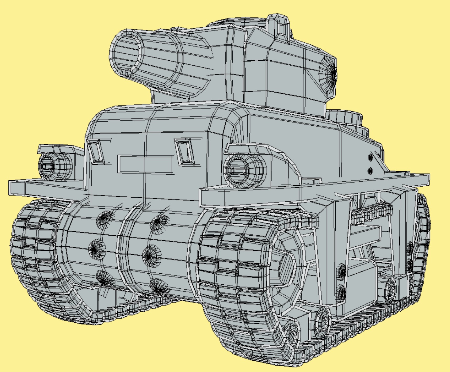
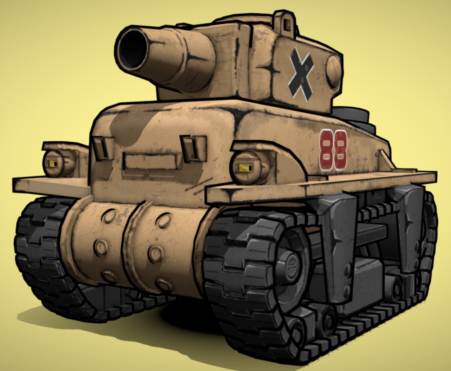
How this works is that for each vertex as well as specifying a 3D x,y,z value we also specify an offset into a texture that should be used to texture that particular part of the model, known as texture coordinates (u, v).
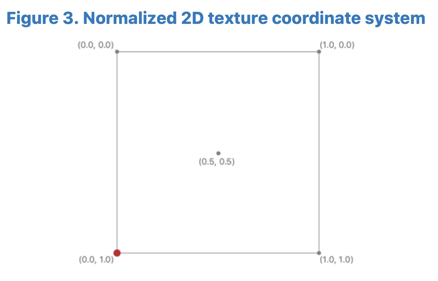
In Metal we can specify texture coordinates in either pixel values or normalized values. Normalized texture coordinates are simply values from 0 to 1, with the top left being (0, 0) and the bottom right being (1,1).
It’s simple to load a texture using the MTKTextureLoader class from MetalKit. There are a number of options to load from a URL, or from the app bundle.
let texLoader = MTKTextureLoader(device: device)

return try? texLoader.newTexture(
  name: "myImage",
  scaleFactor: 1.0,
  bundle: nil,
  options: [:]
)
Once we have the MTLTexture instance there is one more piece we need, a sampler.
MTLSamplerDescriptor / MTLSamplerState
Once you have a texture you need to tell Metal how it should calculate the pixel color for different situations. For example is the caller going to pass normalized texture coordinates (0,0 → 1,1) to access the pixels or actual pixel offsets (100, 250). What should happen if the caller passes in a texture coordinate outside of the texture bounds e.g. (1.25, 0.9). How should the GPU calculate pixel values if the texture is much larger or smaller than the size it is being displayed on the screen and the texture has to be scaled up or down.
All these settings we specify in a MTLSamplerDescriptor then use that to create the MTLSamplerState.
let samplerDescriptor = MTLSamplerDescriptor()
samplerDescriptor.normalizedCoordinates = true
samplerDescriptor.minFilter = .linear
samplerDescriptor.magFilter = .linear
samplerDescriptor.mipFilter = .linear
guard let sampler = device.makeSamplerState(descriptor: samplerDescriptor) else {
  return
}
You will want to keep the MTLSamplerState object around as long as you need the MTLTextureInstance. You can also use the same sampler with multiple textures if they all have the same settings.
Once you have the sampler state, you will want to pass both the texture and the sampler to the fragment shader, using your MTLRenderPassEncoder instance:
encoder.setFragmentTexture(texture, index: 0)
encoder.setFragmentSamplerState(sampler, index: 0)
Here we bind both the texture and sampler to slots 0, then in the fragment shader you can access them both to choose a pixel value e.g.
fragment float4 texture_fragment( (1)
  VertexOut fragIn [[stage_in]], (2)
  texture2d<float, access::sample> diffuseTexture [[texture(0)]], (3)
  sampler diffuseSampler [[sampler(0)]]) { (4)

  return diffuseTexture.sample(diffuseSampler, fragIn.tex).rgba; (5)
}| 1 | You specify a fragment shader by prefixing the function with the "fragment" keyword |
| 2 | The input to the fragment shader is the output from the Vertex shader, which has been interpolated by the GPU so that the values in the vertex are interpolated across the rasterized values sent to the pixel shader. |
| 3 | Our texture is bound to texture slot 0. |
| 4 | Our sampler is bound to sampler slot 0 |
| 5 | We access the pixel value of the texture by passing in the sampler and the texture coordinates (u,v) to the sample method. |
Memory Layout
Size / Stride / Alignment
Before we talk about the last type MTLVertexDescriptor, it is important that we understand how Swift + Metal layout the underlying bytes for the data that we use to communicate between the Swift code and the Vertex shader.
Since we are creating raw blocks of memory in our buffers and populating them with values, we need to be very sure that the layout of the bytes we write in to the buffer in Swift matches up with what the Vertex shader expects for the layout of the input structs. If these don’t line up properly you will end up with garbage output on your screen.
In Swift we have the MemoryLayout enum that can be used to query how different types are laid out in memory. There are three different terms to discuss when talking about memory:
- Size
-
Size represents the total number of bytes that must be copied in order to preserve the value of the item. For example, if you have an instance of a Float, a Float requires 4 bytes in memory, therefore if you have a pointer to the start of the float value you need to copy 4 bytes from the start in order to transfer it somewhere else.
- Stride
-
Stride represents the total number of bytes from the start of one instance of a type to the next in a contiguous block of memory like an array. So if we have a type T and an array of instances e.g [T0, T1, T2 …] for reasons we see below if you simply sum up all the sizes of the fields in the type that might not be the same as the memory offset of T1, due to extra empty padding being added between the fields of the type. It is true that stride(T) >= size(T).
- Alignment
-
When the computer reads or writes values it does it in chunks of memory, maybe 4 bytes, 8 bytes or more. Most CPUs can only handle reading/writing data on these chunk boundaries, you can’t write a value across a boundary. For example, if you have an Int that is 4 bytes, we could write it at memory address 0, or memory address 4, but if we were to try to write the int starting at memory address 2 this would potentially cause a crash across a chunk boundary. Therefore when writing values to memory we need to know the alignment requirements of the type to see what addresses we are allowed to write to.
Let us look at an example to clarify these terms. Image we have a struct that contains an Int and a Bool, looking at the size/stride/alignment values for Int and Bool individually we see that a Bool takes 1 byte to store and that an Int (in this case a 64bit int) takes 8 bytes. The size, stride and alignment values are all the same.
MemoryLayout<Bool>.size       // 1
MemoryLayout<Bool>.stride     // 1
MemoryLayout<Bool>.alignment  // 1

MemoryLayout<Int>.size        // 8
MemoryLayout<Int>.stride      // 8
MemoryLayout<Int>.alignment   // 8
Now let’s define an Account struct that contains an amount and an active field. Looking at the values above, we should be able to add up the Int + Bool values and get a size of 9 bytes for this struct, but what about the stride and alignment values?
struct Account {
  let amount: Int
  let active: Bool
}

MemoryLayout<Account>.size       // 9
MemoryLayout<Account>.stride     // 16
MemoryLayout<Account>.alignment  // 8
As you can see, the stride is 16 bytes and the alignment is 8. What this means is that if we have an array of Account structs and wanted to copy their memory to another location, we couldn’t just say copy (9 * numberItems) bytes, we would end up not copying all the bytes but infact we have to copy (16 * numberItems) bytes.
This is how an array of Account would look like in memory:
I == Int Byte, B == Bool Byte, P == Padding Byte
I I I I I I I I B P P P P P P P I I I I I I I I B P P P P P P P …
The reason for the empty padding at the end of the first Account instance is that as we saw above the alignment of the Int type is 8, what that means is it can only be written to addresses that are divisible by 8. As we can see if we try to write it to byte 10 then it will be spread across the chunk boundaries, hence it is written at the first available address that is divisible by 8 after the end of the first account instance, which is byte 16.
Now you can see why when you put items together in memory contiguously you might have holes that you need to take account of when copying. In our case, we just need to always make sure that when we are copying data into our buffers we use the "stride" value not the "size".
So now what happens if we swap the order of the fields in our Account type? Instead lets define it as:
struct Account {
  let isActive: Bool
  let amount: Int
}

MemoryLayout<Account>.size       // 16
MemoryLayout<Account>.stride     // 16
MemoryLayout<Account>.alignment  // 8
Interesting, now the size changed to 16 instead of 8, but the stride stayed the same. Remember that the size field says what the total number of bytes you need to copy to copy all of the data in a single instance of the struct. What has happened is that the Bool alignment is 1 so it happily goes in byte 1 (it could be written to byte 2, 3, 4 , 5 etc and so on no problem). However the Int alignment is 8, so it can’t be copied into byte 2, that is not divisible by 8, so we have to add some padding until we get to byte 8 to write it.
Now the layout in memory looks like:
I == Int Byte, B == Bool Byte, P == Padding Byte
B P P P P P P P I I I I I I I I B P P P P P P P I I I I I I I I …
floatN / packed_floatN
Given the information above, the main point to take away is to make sure when you are writing values to a buffer in Swift and defining structs in a shader, you understand the size, stride and alignment of the types you are using, on both sides.
There are some common types you will use in a shader, namely float2, float3, float4 for your position, normal, color, texture information etc. These let you use vector float data like:
float3 position = float3(1.0, 2.0, 3.0);

// position.x, position.y, position.z
At first glance you might think those structs are 8, 12 and 16 bytes long (2 * 4, 3 * 4, 4 * 4), seems reasonable, so you go ahead and define a struct in MSL that will be your incoming vertex data.
struct VertexIn {
  float3 position;
};
Then on the Swift side, you create a vertex buffer and write individual floats in to the buffer. To do this we will just create a struct with three floats in it that will then be copied in to the buffer. We populate the buffer with some points that create a simple quad centered around (0,0,-5)
struct Vertex {
  let x, y, z: Float

  func toArray() -> [Float] {
    return [x, y, z]
  }
}

// Define a simple quad with two triangles
// x1 ------ x2
// |         |
// |         |
// x0 ------ x3
let halfSize: Float = 0.5
let z: Float = -5
let vertices: [Vertex] = [
  // Triangle 0
  Vertex(x: -halfSize, y: -halfSize, z: z),  // x0
  Vertex(x: halfSize, y: halfSize, z: z),    // x2
  Vertex(x: -halfSize, y: halfSize, z: z),   // x1

  // Triangle 1
  Vertex(x: -halfSize, y: -halfSize, z: z),  // x0
  Vertex(x: halfSize, y: -halfSize, z: z),   // x3
  Vertex(x: halfSize, y: halfSize, z: z),    // x2
]

// Put all the values in to one array
var data = [Float]()
for vertex in vertices {
  data += vertex.toArray()
}

// Create the buffer
let size = MemoryLayout<Vertex>.stride * vertices.count
meshBuffer = device.makeBuffer(bytes: data, length: size, options: [])
We then define a simple fragment shader that just returns the color red, and a simple vertex shader. Let’s define the vertex shader without using vertex descriptors this time:
struct VertexIn {
  float3 position; (1)
};

struct VertexOut {
  float4 position [[position]];
};

vertex VertexOut vertexShader(
  const device VertexIn* vertices [[buffer(0)]], (2)
  constant Uniforms & uniforms [[buffer(1)]],
  unsigned int vid [[vertex_id]]) (3)
{
  VertexOut vOut;
  float4 position = float4(vertices[vid].position, 1.0);
  vOut.position = uniforms.projectionMatrix * uniforms.modelViewMatrix * position;
  return vOut;
}

fragment float4 fragmentShader(VertexOut in [[stage_in]]) {
  return float4(1.0, 0, 0, 1.0); (4)
}| 1 | This is the definition of the vertex data in the vertex buffer |
| 2 | Pointer to the vertex buffer |
| 3 | The vertex id tells us which vertex in the buffer we should be operating on |
| 4 | Simply return red for all the pixels |
Here is what we are expecting to see, a red quad in the middle of the screen:

However when we run the code we end up seeing:
That’s annoying. So what happened, somehow the x,y,z values we passed to the shader are incorrect. We go back to the Metal Shader Language specification and look at the size/alignment values for the floatN types and we see:
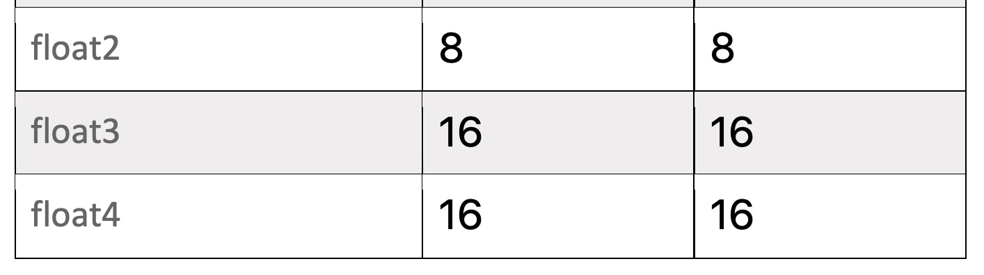
Notice how the float3 actually has an alignment of 16 bytes, not 12 as we expected! Even though it only exposes 3 floats in the code, it is expecting there is an extra byte of padding after each value. Knowing this we go back to the code and change our struct to add an extra float value in the array:
struct Vertex {
  let x, y, z: Float
  let padding: Float = 0.0

  func toArray() -> [Float] {
    return [x, y, z, padding]
  }
}
Now everything renders as expected.
However instead of updating our Vertex structure in Swift, we could leave it as it was without the padding value and choose the packed_float3 type instead of float3 in our shader. The packed_float3 type specifies we are expecting 3 float values for each item in the array without any padding.
struct VertexIn {
  packed_float3 position;
};
SIMD
A quick note on SIMD types. Swift added native support for SIMD data types. SIMD stands for Single Instruction Multiple Data, they are hardware supported operations that allow multiple operations on data at once.
For example, if we had a 3D position stored as an x, y and z value, we could update the position by adding another value:
let x = 1.0
let y = 2.0
let z = 3.0

let xDelta = 5.0
let yDelta = 10.0
let zDelta = 15.0

let newX = x + xDelta
let newY = y + yDelta
let newZ = z + zDelta
Here we take each individual component and add some delta to it to create a new value. However if we use SIMD types we can update all three values at once in a single CPU instruction
let pos: SIMD3<Float> = [1.0, 2.0, 3.0]
let delta: SIMD3<Float> = [5.0, 10.0, 15.0]
let newPos = pos + delta
As well as providing a performance benefit, it’s easier to code with the SIMD types to perform additions, multiplications and vector/matrix operations so you will see them used in the code.
Note that as well as Swift supporting SIMD, the types also match the floatN types we saw in our shaders, so you can directly copy an array of SIMD instances and reference them in your shader using floatN. Also the SIMD3<Float> type also has a stride of 16 not 12 :)
MemoryLayout<SIMD3<Float>>.size       // 16
MemoryLayout<SIMD3<Float>>.alignment  // 16
MemoryLayout<SIMD3<Float>>.stride     // 16
MTLVertexDescriptor
A MTLVertexDescriptor instance lets us tell Metal how the data in the vertex buffer is laid out in memory so that in the vertex shader we can access it correctly.
As we have seen above we don’t actually need vertex descriptors to use Metal shaders, but they have some benefits in that you can change the layout and organization of your buffer data without affecting the vertex shader as much. This lets you do things like use multiple individual buffers for data, one for positions, one for color, one for normals, instead of interleaving all of those values in one buffer.
The general idea is that the vertex descriptor says what data is in the buffer, what type of data it is float3, float4 etc then also which buffers the data is bound to. This information lets us simplify the vertex shader code.
As an example, let’s take our simple quad above, now we define an MTLVertexDescriptor:
let descriptor = MTLVertexDescriptor()

// position x,y,z
descriptor.attributes[0].format = .float3
descriptor.attributes[0].bufferIndex = 0
descriptor.attributes[0].offset = 0
descriptor.layouts[0].stride = MemoryLayout<Vertex>.stride

pipelineDescriptor.vertexDescriptor = descriptor
Now in our shaders we update the VertexIn struct to add an attribute that tells it which attribute in the descriptor it maps to. We also update our vertex function definition to take a different input with a stage_in attribute. This just tells the Metal shader compiler to automatically figure out from the descriptor how to piece together this struct, also no more vertex_id is needed.
struct VertexIn {
  float3 position [[attribute(0)]]; (1)
};

struct VertexOut {
  float4 position [[position]];
};

vertex VertexOut vertexShader(
  const VertexIn vIn [[stage_in]],
  constant Uniforms & uniforms [[buffer(1)]])
{
  VertexOut vOut;
  float4 position = float4(vIn.position, 1.0);
  vOut.position = uniforms.projectionMatrix * uniforms.modelViewMatrix * position;
  return vOut;
}| 1 | Notice how we are using float3 and not packed_float3, this is because packed_floatN types are not allowed with attributes. |
| There is one important thing to note here, which is the main take away. On the Swift side we are passing in x,y,z,x,y,z,x,y,z in the vertex buffer, as we saw float3 in the shader is actually expecting 4 floats for each float3 instance (alignment of 16), so this code broke before but now it works, how? |
Turns out if you use a MTLVertexDescriptor and specify .float3 as the format, the Metal Shader can see that on the client side you are passing just 3 floats but the shader is expecting 4 under the hood and will just pad the last float with 0 automatically for you, magic! This was a bit confusing when I first ran this code and expected it to break. See the docs on MTLVertexAttributeDescriptor for more information.
3D Engine
Now that we have a good understanding of all the pieces required to make a Metal app, let’s start creating the core types we will need to render something on the screen.
Disclaimer
There are an infinite number of ways you can write a 3D engine. The way I have laid out this code is not the "one true way", it’s one way but depending on your requirements, how performant you want your code to be, how maintainable you want the code etc, those will all factor in to how your code is laid out. This code really gives you a starting point to where you can play around with Metal and start writing a more comprehensive and complex engine.
Once looking and playing around with this code I would really recommend trying out other 3D engines, they all have similar concepts but expose them in different ways. I actually really like SceneKit, it’s a very nice library build on top of Metal, but there are also plenty of other engines you can look at like Unity or even things like XNA (one of my favorites back in the day) that will help you learn more about 3D engine design.
Overview
There are a couple of main types in our Engine. How they all fit together is pretty simple:
Renderer
 |- Scene
   |- Camera
   |- Node
    |- Mesh?
     |- Material
      |- Texture?
    |- Node
    |- Node
     |- ...
- Renderer
-
An abstraction around the GPU. This class creates the device and command buffer and then create a single scene object that can be populated with content.
- Scene
-
The scene contains the root node which all content will be added to. Right now our scene is pretty bar bones but we will be adding extra functionality later.
- Node
-
A node contains a mesh. The node lets you specify where in the world the mesh should be rendered based on the rotation, scaling and translation transforms. You can think of the mesh as just defining the model in local space, then the Node providing the information on how to take those local coordinates and move them in to the right place in the world. It also can contain other child nodes to create a hierarchical structure. The Mesh value is optional, a node doesn’t have to have a Mesh, it can simply be a container for other nodes.
- Mesh
-
A mesh contains all of the 3D vertices data needed to render the object. It also keeps a reference to the material used to render the model.
- Material
-
The material defines how the model should look on the screen. Should it be a solid color, texture etc. It’s really an abstraction around the vertex and fragment shader setup.
- Texture
-
A texture just contains the MTLTexture and MTLSamplerState objects and provides a helper method to load new textures.
Vec2 / Vec3 / Vec4 / Mat4
We need some simple vector and matrix classes to use in our engine. Luckily Swift already has support for optimized Vector like types in the SIMD types.
These types however are pretty verbose, it gets old typing the generic version of these so I just type aliased them to shorter friendly names:
typealias Vec2 = SIMD2<Float>
typealias Vec3 = SIMD3<Float>
typealias Vec4 = SIMD4<Float>typealias Mat4 = float4x4typealias Quaternion = simd_quatfIn the Mat file I also added some extension helper methods to make using the types a bit easier such as Mat4.scale(…), Mat4.rotate(…), Mat4.translate(…).
| As of the time of writing there seems to be a bug in the swift compiler around the generic SIMD types that makes compilation times really long in certain cases, or you may see errors where the swift compiler throws up it’s hands and says it can’t figure out the types (never seen this in a compiler before). Hopefully Apple fixes this soon but if you see long compile times you might have to break down your statements into simpler parts of provide more type information to the compiler to help it out. https://forums.swift.org/t/has-type-checking-operators-on-generic-types-always-been-this-slow/23413 |
Renderer
There are some objects, such as MTLDevice, MTLCommandQueue that are long living and need to be passed around the app. We are going to create a high level Renderer class that will help instantiate these objects and also keep track of them.
This is also going to be the class that implements the MTKViewDelegate protocol, so that we get updates when the view size changes (which is necessary to calculate our camera paraemeters later) and also the per frame callback we will use to kick off our rendering.
import MetalKit

final class Renderer: NSObject {

  let device: MTLDevice
  let library: MTLLibrary
  let commandQueue: MTLCommandQueue

  init?(mtkView: MTKView) {

    guard let device = MTLCreateSystemDefaultDevice() else {
      print("Metal is not supported")
      return nil
    }
    self.device = device

    guard let library = device.makeDefaultLibrary() else {
      print("Failed to make default library")
      return nil
    }
    self.library = library

    guard let commandQueue = device.makeCommandQueue() else {
      print("Failed to make a command queue")
      return nil
    }
    self.commandQueue = commandQueue

    self.mtkView = mtkView
    mtkView.device = device

    // Specifies the pixel format to use for the buffer that will be rendered
    // to the screen
    mtkView.colorPixelFormat = .bgra8Unorm_srgb

    // The format to use in the depth stencil. This is used to determine which parts
    // of a model are visible.
    mtkView.depthStencilPixelFormat = .depth32Float

    super.init()
  }

}

extension Renderer: MTKViewDelegate {

  func mtkView(_ view: MTKView, drawableSizeWillChange size: CGSize) {
  }

  func draw(in view: MTKView) {
  }
}
Scene
For any situation where we have more that one object to draw we will want some kind of container that we can add Nodes to and keep track of them. The scene object will be this container. We will add a root property to the Scene which will be the top level Node for all nodes in our scene.
There will only be one Scene instance and it will be created in the Renderer at creation time.
As well as storing the root Node instance, the Scene class will also store the clear color, this is the color we use for every new frame as the background. Finally we also store the camera in the scene, the camera can be used to view the scene from different locations, just like a camera in the real world.
import Metal

public final class Scene {

  /// The top level node in our entire scene
  public let root = Node()

  /// A camera used to view the content of the scene
  public var camera: PerspectiveCamera

  /// A color that will be used as the background for every new frame
  public var clearColor: MTLClearColor = MTLClearColor(
    red: 0.0,
    green: 0.0,
    blue: 0.0,
    alpha: 1.0
  )

  init() {
    camera = PerspectiveCamera(
      origin: [0, 0, 5],
      look: [0, 0, -1],
      up: [0, 1, 0],
      fovYDegrees: 90,
      aspectRatio: 1.0,
      zNear: 0.001,
      zFar: 1000.0
    )
  }

  func update(time: Time) {
    root.updateInternal(time: time) (1)
  }

  func render(
    time: Time,
    renderer: Renderer,
    encoder: MTLRenderCommandEncoder,
    uniformBuffer: MTLBuffer
  ) {

    root.render(
      time: time,
      camera: camera,
      renderer: renderer,
      encoder: encoder,
      parentTransform: Mat4.identity
    )

  }
}| 1 | The update function will let us apply an update closure to each node that can be used to do per frame updates and animations. |
PerspectiveCamera
We need a camera so that we can move around the scene and set properties such as the field of view to control how zoomed in or out the scene will be. We will only support Perspective Projection in our engine, however adding Orthographic projection would be trivial by creating a Camera protocol that both a PerspectiveCamera and OrthographicCamera could implement.
The camera is pretty simple, it exposes a viewMatrix and projectionMatrix property, these matrices are recalculated if the user changes any of the property of the camera. We then take these matrices and pass them to our vertex shader with a uniform buffer.
final class PerspectiveCamera {

  var origin: Vec3 { didSet { buildView = true } }
  var look: Vec3 { didSet { buildView = true } }
  var up: Vec3 { didSet { buildView = true } }
  var fovYDegrees: Float { didSet { buildProjection = true } }
  var aspectRatio: Float { didSet { buildProjection = true } }
  var zNear: Float { didSet { buildProjection = true } }
  var zFar: Float { didSet { buildProjection = true } }

  private var buildProjection = true
  private var buildView = true
  private var _projectionMatrix = Mat4.identity
  private var _viewMatrix = Mat4.identity

  var projectionMatrix: Mat4 {
    get {
      if buildProjection {
        buildProjection = false
        _projectionMatrix = Math.makePerspective(
          fovyDegrees: fovYDegrees,
          aspectRatio: aspectRatio,
          nearZ: zNear,
          farZ: zFar
        )
      }
      return _projectionMatrix
    }
  }

  var viewMatrix: Mat4 {
    get {
      if buildView {
        buildView = false
        _viewMatrix = Math.makeLook(eye: origin, look: look, up: up)
      }
      return _viewMatrix
    }
  }

  init(
    origin: Vec3,
    look: Vec3,
    up: Vec3,
    fovYDegrees: Float,
    aspectRatio: Float,
    zNear: Float,
    zFar: Float
  ) {
    self.origin = origin
    self.look = look
    self.up = up
    self.fovYDegrees = fovYDegrees
    self.aspectRatio = aspectRatio
    self.zNear = zNear
    self.zFar = zFar
  }

}
Mesh
A mesh contains all of the 3D vertex data for the model and also the material that should be used to render the model (solid color, texture etc).
The mesh is then responsible for setting the vertex buffer in the rendering pipeline and actually submitting the final draw command.
import MetalKit

public final class Mesh {

  public struct VertexBuffer {
    public let buffer: MTLBuffer
    public let bufferIndex: Int
    public let primitiveType: MTLPrimitiveType
    public let vertexCount: Int

    public init(buffer: MTLBuffer, bufferIndex: Int, primitiveType: MTLPrimitiveType, vertexCount: Int) {
      self.buffer = buffer
      self.bufferIndex = bufferIndex
      self.primitiveType = primitiveType
      self.vertexCount = vertexCount
    }
  }

  public let vertexBuffer: VertexBuffer
  public var material: Material?

  public init(vertexBuffer: VertexBuffer) {
    self.vertexBuffer = vertexBuffer
  }

  func render(encoder: MTLRenderCommandEncoder) {
    encoder.setVertexBuffer(vertexBuffer.buffer, offset: 0, index: vertexBuffer.bufferIndex)
    encoder.drawPrimitives(
      type: vertexBuffer.primitiveType,
      vertexStart: 0,
      vertexCount: vertexBuffer.vertexCount,
      instanceCount: 1
    )
  }
}
Node
The Node class represents a way to take 3D local data and transform them in to a point in the world. The node has a position, orientation and scale property that you can set to move the content in the world. It also has an optional mesh property, the mesh is used to describe the 3D data associated with the node. Nodes can contain other child nodes, in this way we can create our scene hierarchy of transforms.
public final class Node {
  public var position = Vec3(0, 0, 0)
  public var orientation = Quaternion.identity
  public var scale = Vec3(1, 1, 1)

  /**
   The mesh associated with the node. Note that this is optional, a mesh can just be a container
   for other child nodes and not have any renderable information associated with it.
   */
  public var mesh: Mesh?

  /**
   The update function can be used to modify the node parameters every frame. If this closure is
   present it will be called once before the render call, every frame. You could use this to rotate
   the node etc.
   */
  public var update: ((_ time: Time, _ node: Node) -> Void)?

  /**
   Returns a matrix that is the combination of the position, orientation and scale properties.
   These are applied in scale -> rotate -> translate order.
   */
  public var transform: Mat4 {
    let translate = Mat4.translate(position)
    let s = Mat4.scale(scale.x, scale.y, scale.z)
    return translate * orientation.toMat() * s
  }

  private var children = [Node]()

  public init(mesh: Mesh? = nil) {
    self.mesh = mesh
  }
}
As well as these simple properties, the other main job of the Node is to setup some of the rendering state. If the node has a mesh, we will take the material associated with the mesh and setup the fragment shader. This is also where we pass in the current model matrix to the vertex shader so that it can perform the local → world transform.
func render(
  time: Time,
  camera: PerspectiveCamera,
  renderer: Renderer,
  encoder: MTLRenderCommandEncoder,
  parentTransform: Mat4
) {

  let worldTransform = parentTransform * transform

  // If there is no mesh then this is simply a passthrough node that contains
  // other nodes
  if let mesh = mesh, let material = mesh.material {
    var constants = ModelConstants(modelMatrix: worldTransform)
    encoder.setVertexBytes(&constants, length: MemoryLayout<ModelConstants>.size, index: 1)

    if let texture = material.texture {
      encoder.setFragmentTexture(texture.mtlTexture, index: 0)
      encoder.setFragmentSamplerState(texture.samplerState, index: 0)
    }
    encoder.setRenderPipelineState(material.renderPipelineState)
    mesh.render(encoder: encoder)
  }

  for node in children {
    node.render(
      time: time,
      camera: camera,
      renderer: renderer,
      encoder: encoder,
      parentTransform: worldTransform
    )
  }
}
Material
When you want to render your 3D content, as well as the topology of the model such as the points in 3D space and the relationships between those points, how they compose to make primitives such as triangles or lines, we need to also be able to have some way of changing their visual appearance. This is where shaders come in.
The Material class encapsulates which Vertex + Fragment shader should be used to draw the content, as well as specifying how the data should be stored in the vertex buffer in order for it to be accessed in the shaders. Going back to the Metal types, MTLRenderPipelineState is the object that stores the compiled vertex + fragment shaders, so inside our Material class we are just going to setup one of these objects.
Obviously the shaders require that the vertex buffers have the correct data that the shader needs and also that the caller has put the data in the correct order inside the buffer. If you have put color information where the shader was expecting x,y,z values for a 3D point, you’re going to have a bad time.
import Metal

class Material {
  let renderPipelineState: MTLRenderPipelineState

  init?(
    renderer: Renderer,
    vertexName: String,
    fragmentName: String,
    vertexDescriptor: MTLVertexDescriptor
  ) {
    let descriptor = renderer.defaultPipelineDescriptor()
    let fragmentProgram = renderer.library.makeFunction(name: vertexName)
    let vertexProgram = renderer.library.makeFunction(name: fragmentName)
    descriptor.vertexFunction = vertexProgram
    descriptor.fragmentFunction = fragmentProgram
    descriptor.vertexDescriptor = vertexDescriptor

    guard let state = try? renderer.device.makeRenderPipelineState(descriptor: descriptor) else {
      return nil
    }
    renderPipelineState = state
  }
}
Now that we have this base class, we can create any number of Materials that can be used to render models differently. In Toy3D there is function to create a BasicMaterial which supports solid colors and texturing of models.
extension Material {
  public static func createBasic(renderer: Renderer, texture: Texture?) -> Material? {
    let descriptor = MTLVertexDescriptor()

    // Some vertex buffers are reserved by the render, this gives us the first
    // free vertex buffer that we can use.
    let bufferIndex = Renderer.firstFreeVertexBufferIndex

    // position x,y,z
    descriptor.attributes[0].format = .float3
    descriptor.attributes[0].bufferIndex = bufferIndex
    descriptor.attributes[0].offset = 0

    // normal x,y,z
    descriptor.attributes[1].format = .float3
    descriptor.attributes[1].bufferIndex = bufferIndex
    descriptor.attributes[1].offset = MemoryLayout<Float>.stride * 3

    // color r,g,b,a
    descriptor.attributes[2].format = .float4
    descriptor.attributes[2].bufferIndex = bufferIndex
    descriptor.attributes[2].offset = MemoryLayout<Float>.stride * 6

    descriptor.attributes[3].format = .float2
    descriptor.attributes[3].bufferIndex = bufferIndex
    descriptor.attributes[3].offset = MemoryLayout<Float>.stride * 10

    descriptor.layouts[bufferIndex].stride = MemoryLayout<Float>.stride * 12

    return Material(
      renderer: renderer,
      vertexName: "basic_vertex",
      fragmentName: texture != nil ? "texture_fragment" : "color_fragment",
      vertexDescriptor: descriptor,
      texture: texture
    )
  }
}
Here you see we have specified the vertex and fragment shader we want to use in our .metal file. We also have specified how the data should be laid out in the vertex buffer when using these shaders.
| Notice how we are binding the data to bufferIndex Renderer.firstFreeVertexBufferIndex. Buffers 0 and 1 are bound by data in the engine, so buffer Renderer.firstFreeVertexBufferIndex and up are the free buffers you should use for your own data. If you try to bind to buffers below that things will break. |
Texture
The texture class will represent one texture in the system. It will store a reference to an MTLTexture instance and also to a MTLSamplerState object that is used to access the texture. We also add a simple helper method to load a texture.
import MetalKit

final class Texture {

  let mtlTexture: MTLTexture
  let samplerState: MTLSamplerState

  init(mtlTexture: MTLTexture, samplerState: MTLSamplerState) {
    self.mtlTexture = mtlTexture
    self.samplerState = samplerState
  }

  /// Loads a texture from the main bundle with the given name
  static func loadMetalTexture(device: MTLDevice, named: String) -> MTLTexture? {
    let texLoader = MTKTextureLoader(device: device)
    return try? texLoader.newTexture(
      name: named,
      scaleFactor: 1.0,
      bundle: nil,
      options: [.generateMipmaps : true]
    )
  }
}guard let mtlTexture = Texture.loadMetalTexture(device: renderer.device, named: "myImage") else {
return
}
let descriptor = MTLSamplerDescriptor()
descriptor.normalizedCoordinates = true
descriptor.minFilter = .linear
descriptor.magFilter = .linear
descriptor.mipFilter = .linear
guard let sampler = device.makeSamplerState(descriptor: descriptor) else {
return
}
let texture = Texture(mtlTexture: mtlTexture, samplerState: sampler)
// Use the texture in our appBasicVertex
We will create a simple struct to help us define some 3D data that will let use provide position, normal, color and texture coordinates for the vertices of a model.
import Metal

/**
 BasicVertex represents a common set of values that you might want to associate with a vertex.

 This one supports position, color, normal and texture coordinates.
 */
public struct BasicVertex {

  // position
  public var x, y, z : Float

  // normal
  public var nx, ny, nz: Float

  // color
  public var r, g, b, a: Float

  // texCoords
  public var u, v: Float

  public init(pos: Vec3, normal: Vec3, color: Vec4, tex: Vec2) {
    x = pos.x
    y = pos.y
    z = pos.z
    nx = normal.x
    ny = normal.y
    nz = normal.z
    r = color.x
    g = color.y
    b = color.z
    a = color.w
    u = tex.x
    v = tex.y
  }

  public func floatBuffer() -> [Float] {
    return [x, y, z, nx, ny, nz, r, g, b, a, u, v]
  }

  /// Given an array of vertices, returns an MTLBuffer containing the vertex data
  public static func toBuffer(device: MTLDevice, vertices: [BasicVertex]) -> MTLBuffer? {
    var data = [Float]()
    vertices.forEach { (vertex) in
      data.append(contentsOf: vertex.floatBuffer())
    }

    let size = MemoryLayout<BasicVertex>.stride * vertices.count
    return device.makeBuffer(bytes: data, length: size, options: [])
  }
}
Time
The Time struct contains two values, one is a totalTime property that is a monotonic increasing value. The other is updateTime which is the time since the last update call. This is useful for animations where you don’t want to just add a fixed amount every frame to an animation e.g. rotationX += 10, since if the frames don’t render at an even rate things will jump, however you can just use the delta to compute how much the value should change based on some fixed amount per unit time.
struct Time {

  /// The total time of the app. This is just a number that is always
  /// increasing, it might not start at 0, just use it for relative calculations
  let totalTime: TimeInterval

  /// The time since the last update call
  let updateTime: TimeInterval
}
Buffers
The way we transfer data to and from the CPU and GPU is through buffers. Buffers are just blocks of memory. As we have seen we can create a new buffer to store our vertex data using device.createBuffer()
However, we don’t just need to pass vertex data to the shaders, we also have other pieces of information, most commonly the projectionMatrix, viewMatrix and modelMatrix that are used to transform the local 3D points in the model to world values that can then be projected in to 2D. The way we pass this information in Metal is the sames as the vertices, we just use a buffer.
The view and projection matrix are constant across all models in the frame, we can create a struct to set them in the Swift code:
struct Uniforms {
  var viewProjection: Mat4
}
Then we can allocate a buffer that will hold the contents of this struct which can be accessed in the vertex shader.
// Create the buffer
guard let uniformBuffer: MTLBuffer? = device.makeBuffer(length: MemoryLayout<Uniforms>.size, options: []) else {
  return
}

// Populate it with some values
let uniformContents = uniformBuffer.contents().bindMemory(to: Uniforms.self, capacity: 1)
uniformContents.pointee.viewProjection = scene.camera.projectionMatrix * scene.camera.viewMatrix

// Bind the buffer to buffer 0
encoder.setVertexBuffer(uniformBuffer, offset: 0, index: 0)
Now on the vertex shader side we access the uniforms by binding to the buffer 0 slot
vertex VertexOut basic_vertex(
  const VertexIn vIn [[ stage_in ]],
  const device Uniforms& uniforms [[ buffer(0) ]]) {

  // ...
}
Synchronizing Memory Access
The above is fine, but there is a subtle problem. If we create a single buffer to be used to store our per frame values and use that across multiple frames, the CPU and GPU may actually be working on different frames at the same time. For example, the CPU sets up frame 0 and submits it, then sets up frame 1 and submits it and so on. The GPU receives these requests and processes them, but it can fall behind the CPU.
Hence it could actually be the case that we populate the uniform buffer with data for frame 0, submit it, then immediately update the uniform buffer with frame 1 values while the GPU is still trying to process frame 0 data. This can happen because the buffer memory is shared between the CPU + GPU.
Because of this we need to make sure that we have separate buffers for each frame that can be written and read from without affecting other frames.
Apple has a great write up on this here. In our engine, we create a buffer pool, each frame can grab a new buffer to store the uniform data, then once it is processed we can return it to the pool. We know when the GPU has completed processing all the commands by using the completed callback on the MTLCommandBuffer instance.
There is a simple class called BufferManager, when you initialize it you say how many buffers you need and how to initiaize those buffers:
let uniformBuffers = BufferManager(device: device, inflightCount: 3, createBuffer: { (device) in
  return device.makeBuffer(length: MemoryLayout<Uniforms>.size, options: [])
})
uniformBuffers.createBuffers()

// Inside the per frame render method

// Get the buffer and update values
let uniformBuffer = uniformBuffers.nextSync()

guard let commandBuffer = commandQueue.makeCommandBuffer() else {
  return
}

// Submit draw commands

// Wait the the commands to complete
commandBuffer.addCompletedHandler { (MTLCommandBuffer) in
  uniformBuffers.release()
}
The BufferManager class uses the DispatchSemaphore class to manage access to the resources.
import Metal

final class BufferManager {

  private let device: MTLDevice
  private let inflightCount: Int
  private var bufferIndex: Int = 0
  private let createBuffer: (MTLDevice) -> MTLBuffer?
  private let semaphore: DispatchSemaphore
  private var buffers: [MTLBuffer]

  /**
   - parameters:
     - device: The metal device
     - inflightCount: The number of buffers to manage
     - createBuffer: a closure that will ne called inflightCount times to create the buffers
   */
  init(device: MTLDevice, inflightCount: Int, createBuffer: @escaping (MTLDevice) -> MTLBuffer?) {
    self.device = device
    self.inflightCount = inflightCount
    self.createBuffer = createBuffer
    semaphore = DispatchSemaphore(value: inflightCount)
    buffers = [MTLBuffer]()
  }

  /// You must call this before calling nextSync()
  func createBuffers() {
    for _ in 0..<inflightCount {
      if let buffer = createBuffer(device) {
        buffers.append(buffer)
      } else {
        print("Failed to create buffer")
      }
    }
  }

  /// Returns the next free buffer. If a buffer is not available this will block the caller
  func nextSync() -> MTLBuffer {
    semaphore.wait()

    let buffer = buffers[bufferIndex]
    bufferIndex = (bufferIndex + 1) % inflightCount
    return buffer
  }

  /**
   Indicates a buffer has been released.

   - note: There is an implicit assumption that buffers are released in the same order
           that they were acquired in.
   */
  func release() {
    semaphore.signal()
  }
}
setVertexBytes
You can also use the MTLRenderCommandEncoder setVertexBytes method to get a temporary buffer from a pool of buffers managed by the device. You can use these buffers for small blocks of data <4KB
| You could also put the per frame values like view, model and projection matrix in the same buffer as your vertex data if you want, it is entirely up to you. You could write those at the beginning of the buffer and then offset the vertex data after them. You can then bind your Vertex shader structs to the same buffer at different offset. There are many ways of passing the data through, some might be more efficient for larger data. |
Model I/O
As well as defining our own Mesh vertex data, we also want to be able to import models from 3rd parties. There are many 3D model formats used in the real world, .obj, .ply, .usd and so on. Model I/O is a framework from Apple that makes it very easy to import and export data from multiple formats. We will add support for Model I/O to our simple engine.
Model I/O has a class called MDLAsset. This class is used to load the external data into Model I/O data structures. Once we have the MDLAsset instance, we can then use MetalKit to create a MetalKit mesh MTKMesh. A MTKMesh can then be used to get access to MTLBuffer instances that we can use to render the model.
In our Mesh class we will support taking in a MTKMesh instance in the initializer:
public final class Mesh {

  public var mtkMesh: MTKMesh?

  public init(mtkMesh: MTKMesh) {
    self.mtkMesh = mtkMesh
  }

  // ...
}
The MTKMesh contains a vertex buffer that has all the 3D vertex data, then also a collection of SubMeshes.
func render(encoder: MTLRenderCommandEncoder) {

    if let mesh = mtkMesh {
      encoder.setVertexBuffer(mesh.vertexBuffers[0].buffer, offset: 0, index: Renderer.firstFreeVertexBufferIndex)

      for submesh in mesh.submeshes {
        encoder.drawIndexedPrimitives(
          type: .triangle,
          indexCount: submesh.indexCount,
          indexType: submesh.indexType,
          indexBuffer: submesh.indexBuffer.buffer,
          indexBufferOffset: submesh.indexBuffer.offset
        )
      }
      return
    }

    // Otherwise just use our own MTL buffer
}
For an example of how to load an MDLAsset see the Examples.swift file in the Sample project: https://github.com/markdaws/metal-example/blob/master/metal-example/Examples.swift
Examples
Now we have all the pieces of our 3D engine in place we can make some examples.
The basic flow will be:
-
Create the Renderer passing in an instance of MTKView
-
Create a Mesh that has all of the 3D vertex information
-
Create a Material to use to describe how the Mesh should look, solid color, textured etc.
-
Create a Node to hold the Mesh instance. Set the transform on the Node to move the Mesh in the world
-
Add the Node to the Scene
-
Profit!
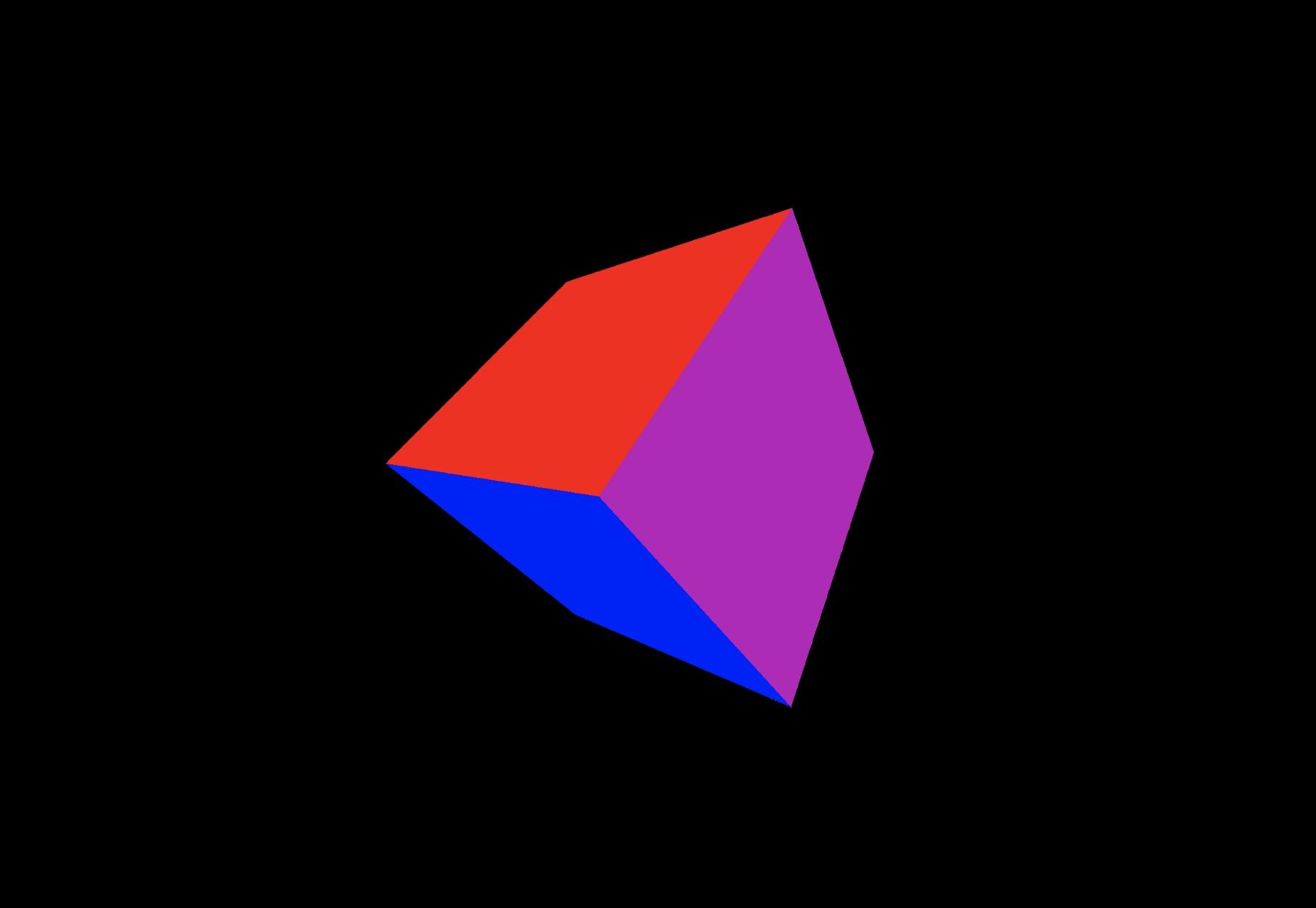
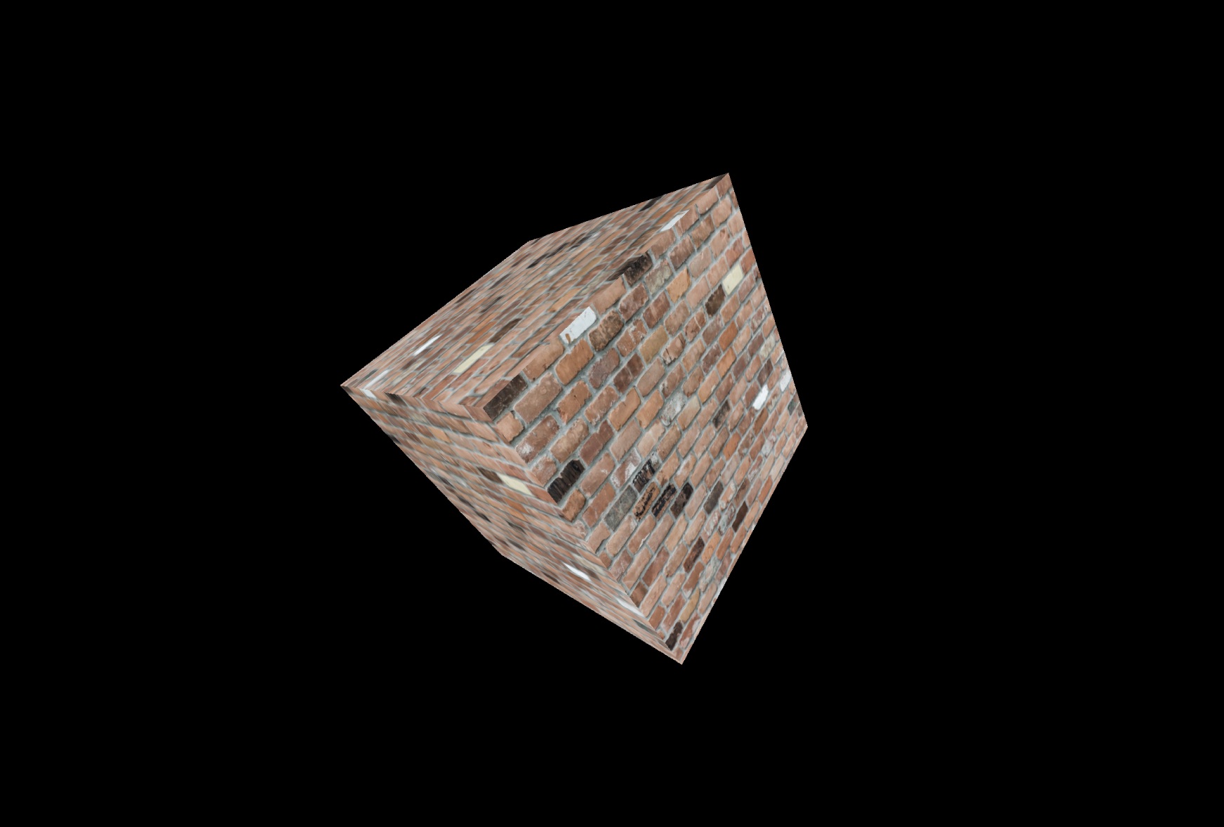
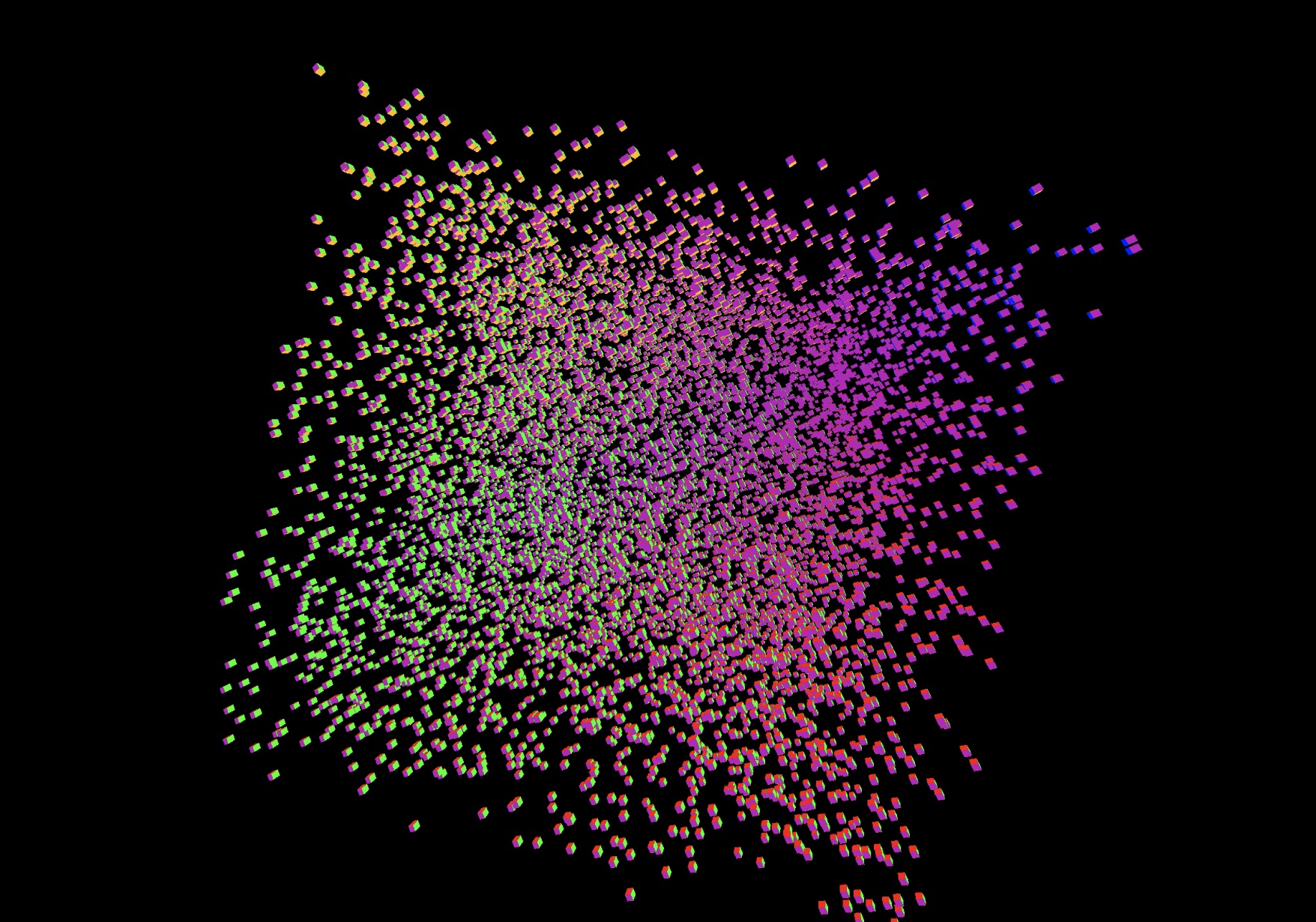
The code to create the cube sample is pretty simple:
func createSingleCube(renderer: Renderer) {

  guard let metalTexture = Texture.loadMetalTexture(device: renderer.device, named: "bricks") else {
    return
  }

  let samplerDescriptor = MTLSamplerDescriptor()
  samplerDescriptor.normalizedCoordinates = true
  samplerDescriptor.minFilter = .linear
  samplerDescriptor.magFilter = .linear
  samplerDescriptor.mipFilter = .linear
  guard let sampler = renderer.device.makeSamplerState(descriptor: samplerDescriptor) else {
    return
  }

  let texture = Texture(mtlTexture: metalTexture, samplerState: sampler)
  let material = Material.createBasic(renderer: renderer, texture: texture)

  // Define the 3D vertices and colors for the vertices
  let dimension: Float = 3.0
  guard let cubeMesh = Primitives.cuboid(
    renderer: renderer,
    width: dimension,
    height: dimension,
    length: dimension) else {
    print("Failed to create the cuboid mesh")
    return
  }
  cubeMesh.material = material

  let node = Node(mesh: cubeMesh)
  node.position.x = 10
  renderer.scene.root.addChild(node)
}
As you can see we create a cube mesh, calling a helper method in the Primitives class, the load our texture from the bundle. Once we have the texture we can create a BasicMaterial that understands texture coordinates and apply it to the mesh. The final piece is to create a node and add it to the scene hierarchy.
Future
Toy3D only scratches the basics of what you can do with a 3D engine. Some immediate improvements we could make are:
-
Lighting Models: we already pass through the normal information through to the vertex shader, this can be used to add basic lighting information.
-
Multiple textures per mesh: Right now we are limited to one material for the entire mesh. It may be that you want to support multiple materials, you could add the concept of a submesh to the mesh class, where each submesh has a material and index in to the overall vertex buffer.
-
Add support for picking objects from the scene i.e. clicking on a model and highlighting it.
And so on :)